| Yard | |||
|---|---|---|---|
| Week 1 | |||
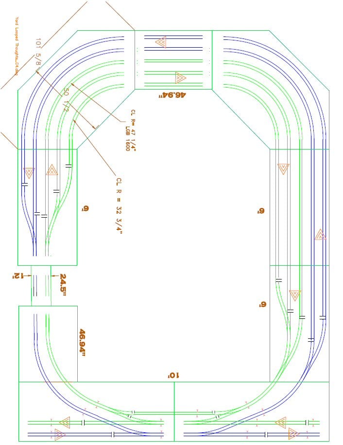 Here is the preliminary redesign for the yard. |
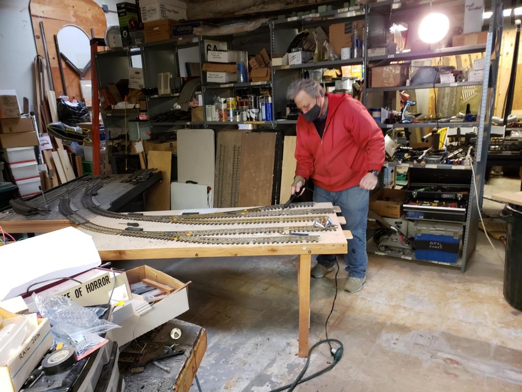
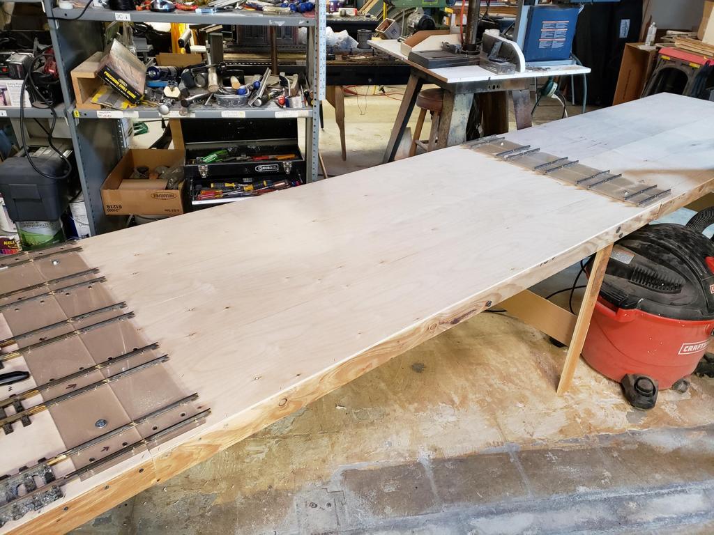
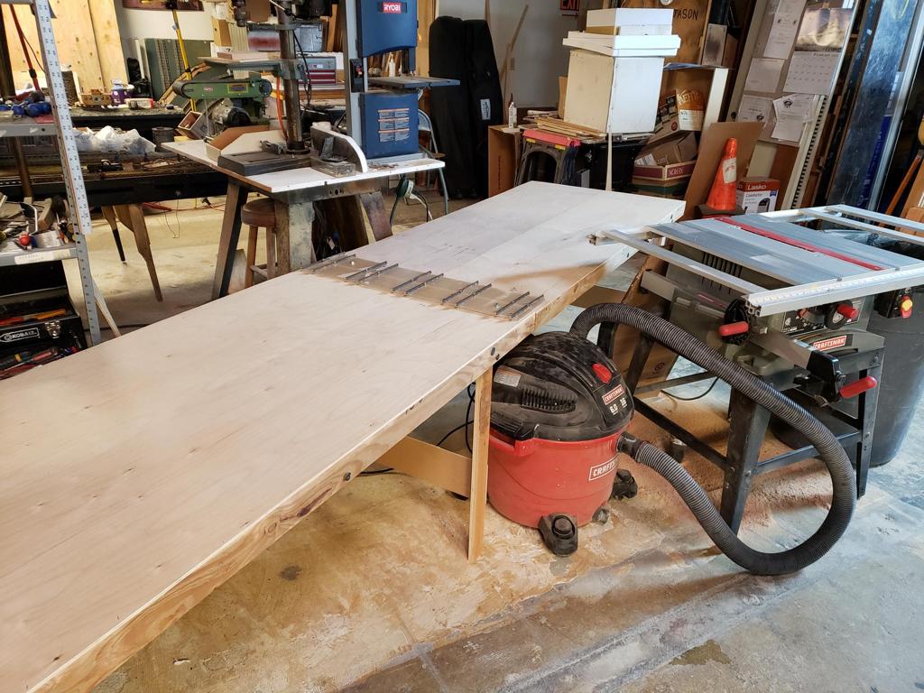
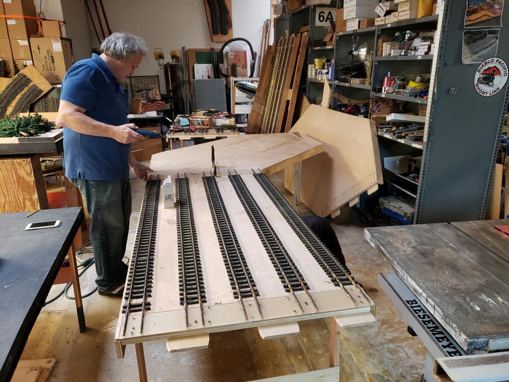
 As part of the redesign, we needed to cut 2 feet off the original mainline modules. In this picture, Bruce and Eric are installing the shelf/end of the east yard module. |
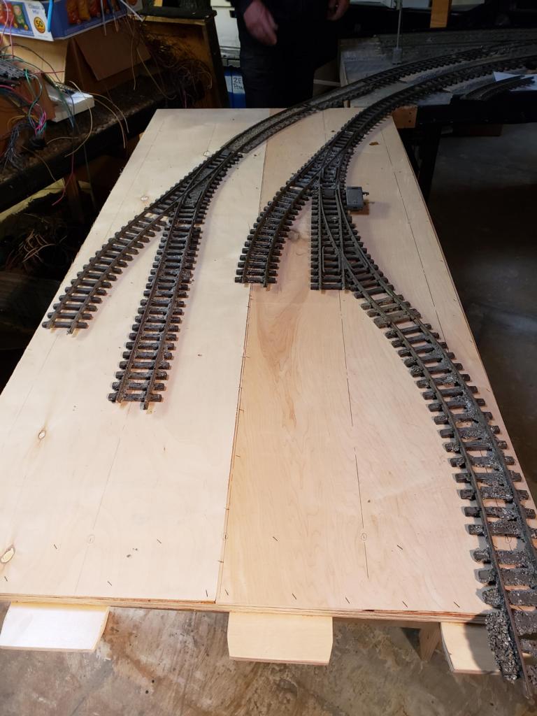
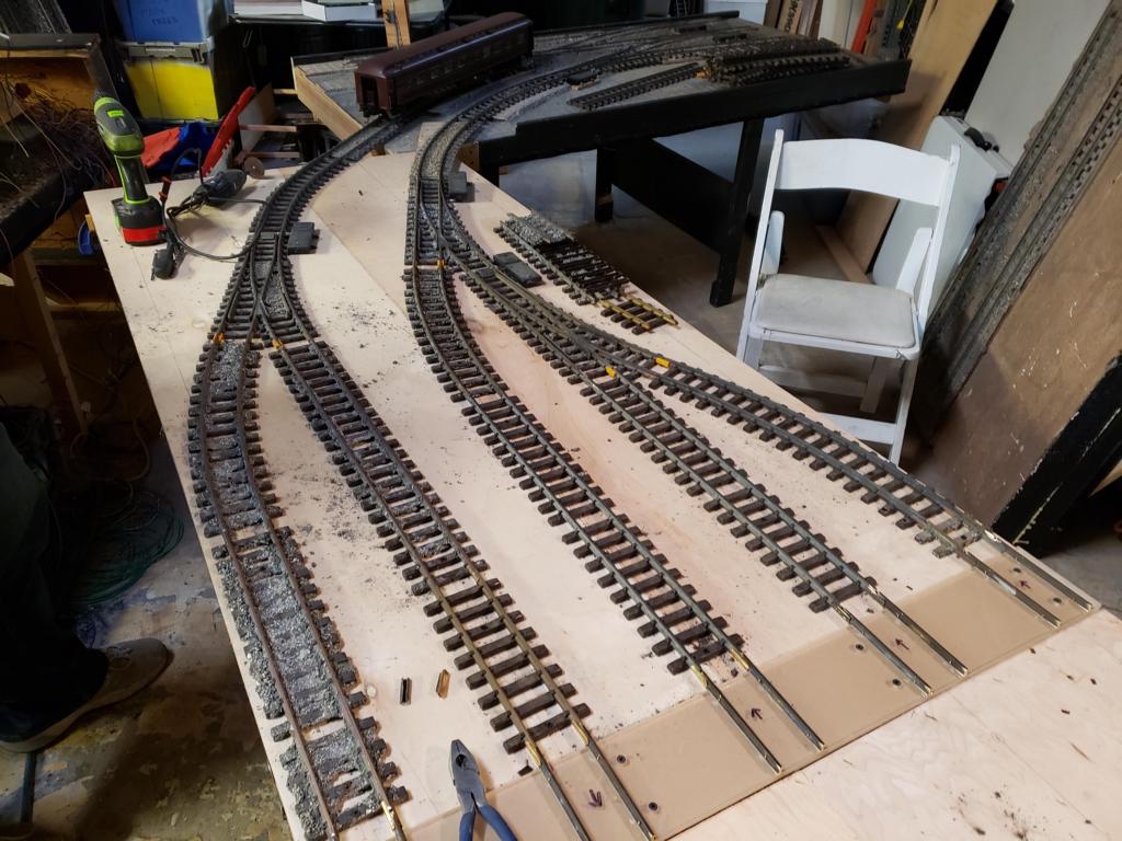
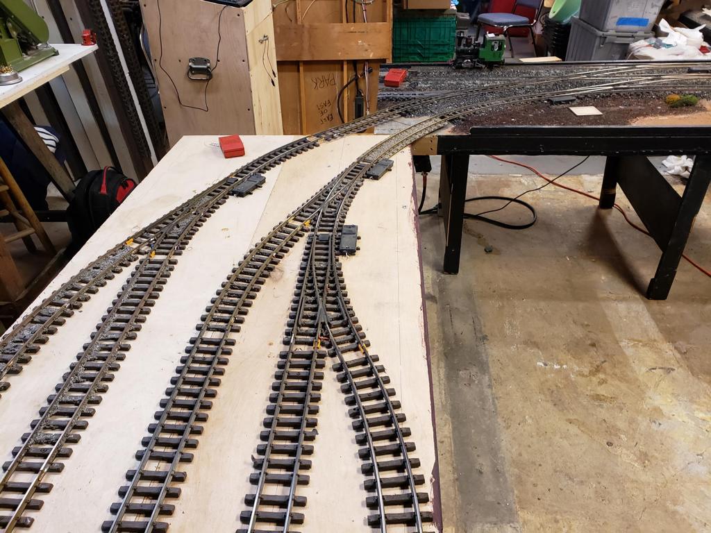
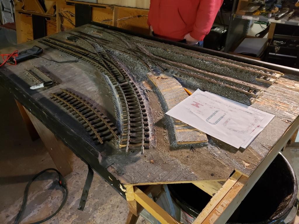 And in this picture and the next, we have begun moving the track to match the redesign of the yard. |
 |
| Week 2 | |||
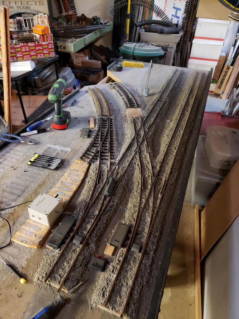
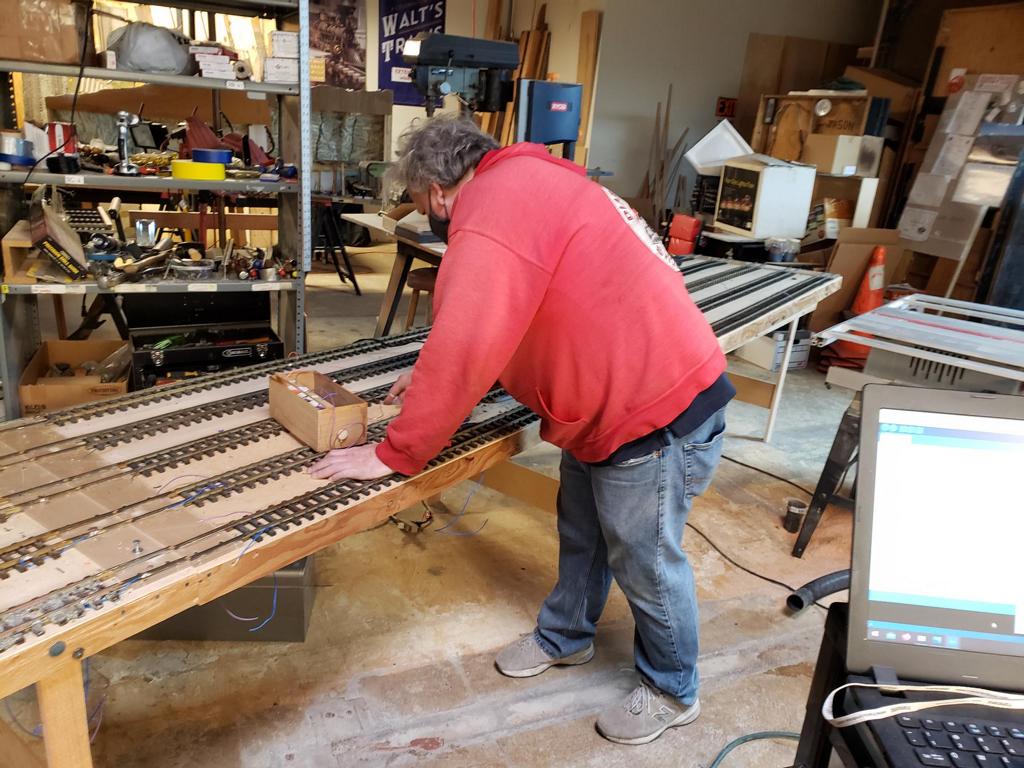
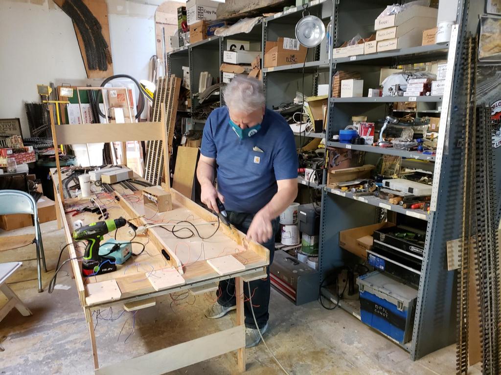
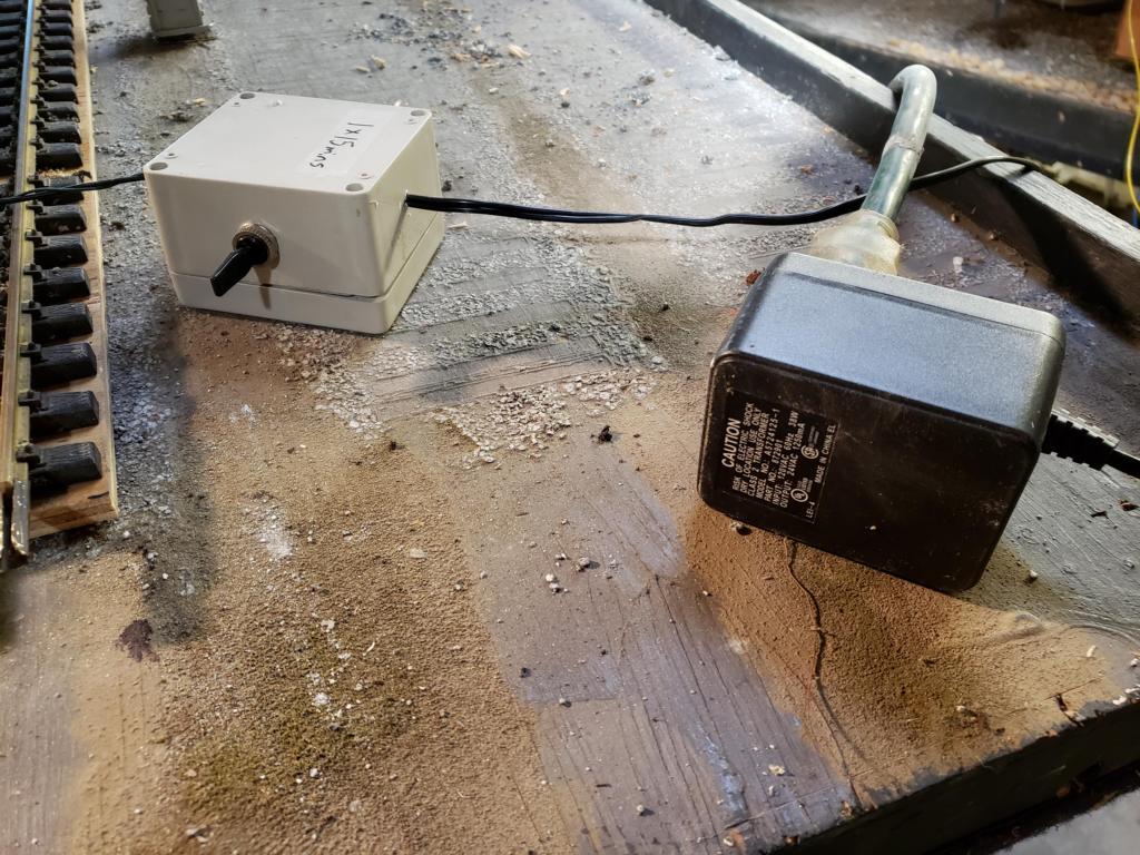 For this week, we installed track feeds on the east yard module. In addition, the switch motors and feedback mechanisms were added. To ensure the switches operate correctly, we use a switch tester (see picture) which sends the appropriate signals depending on the switch position. |
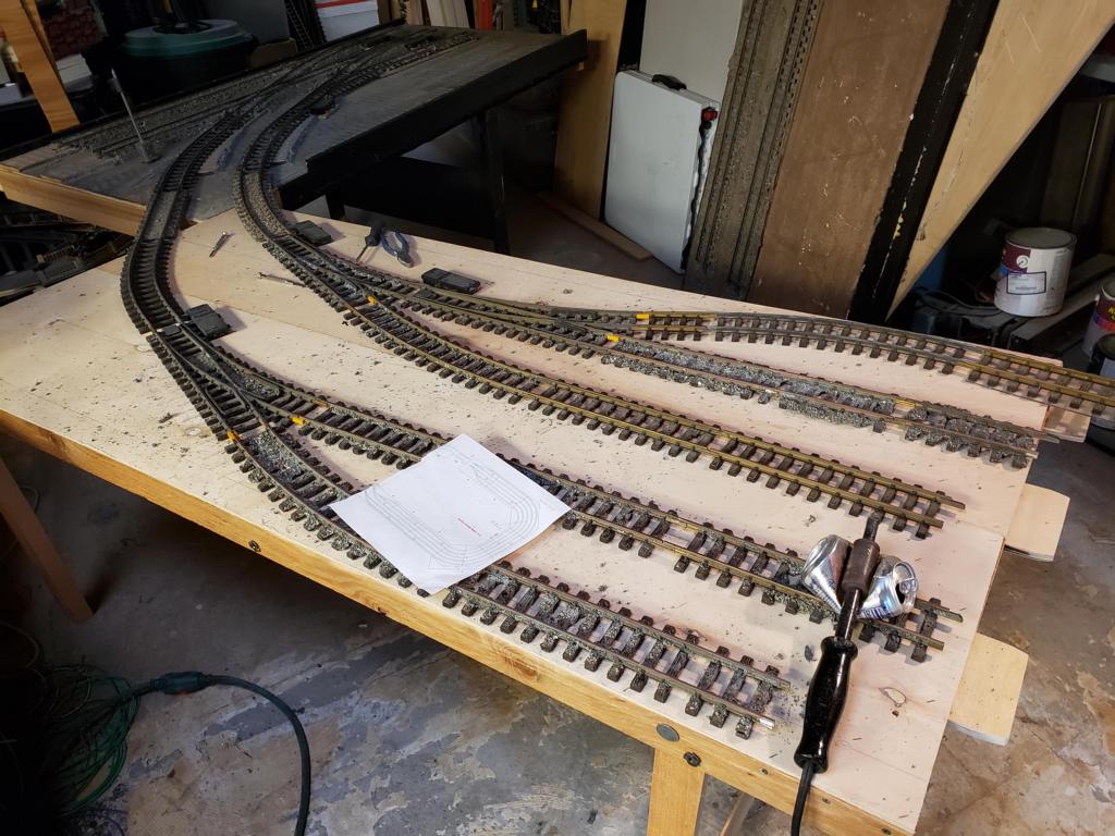
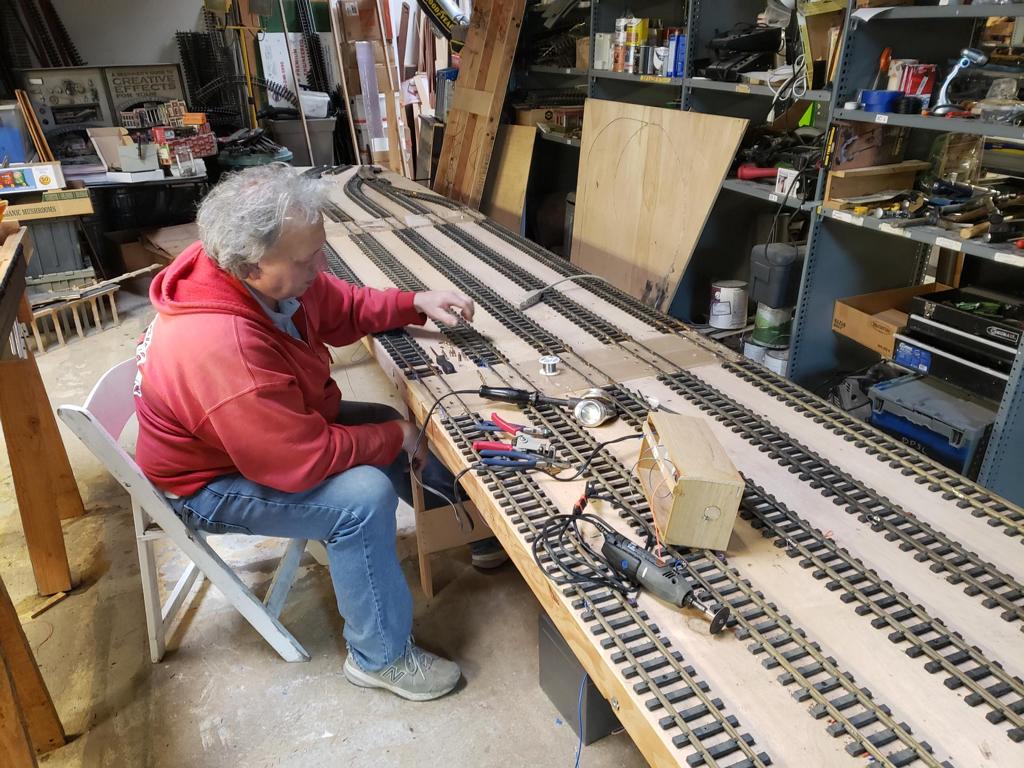
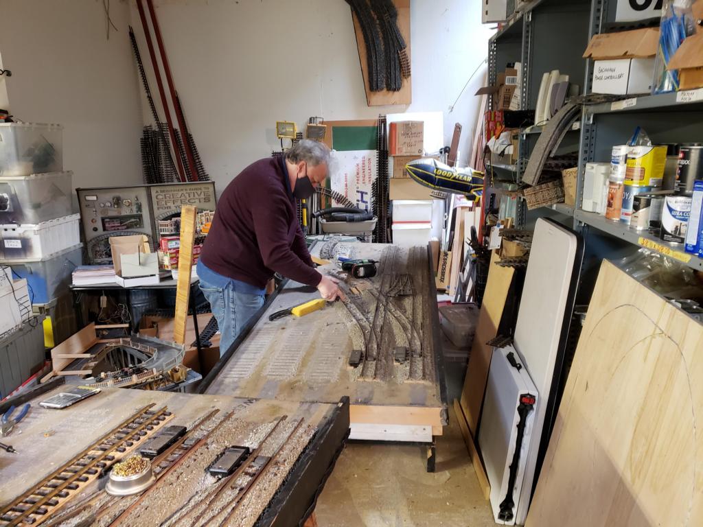 In this picture, Eric has begun prep work on the west yard module. This includes pulling some of the old track (which will not be used in the new design) and installing the new track. |
 As part of the new design, we have begun adding two aspect signals to the yard modules. These signals will change depending upon the switch positions. |
 To finish up the week, we used the switch tester to test the switches and feedback mechanisms on the west yard module. |
| Week 3 | |||
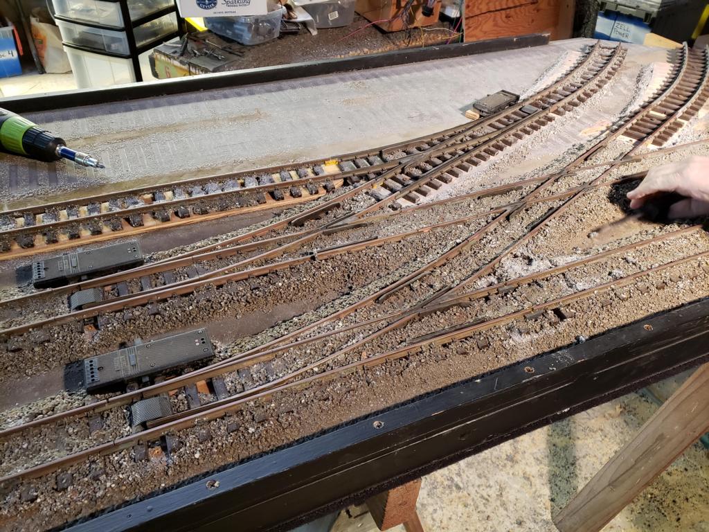
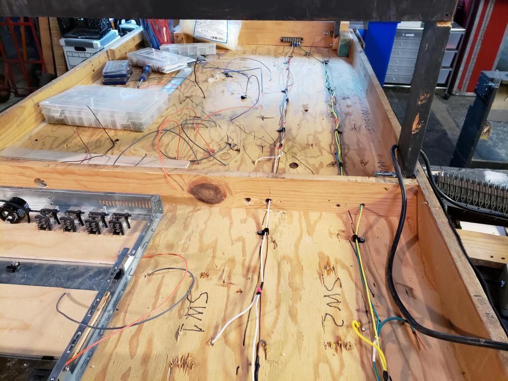
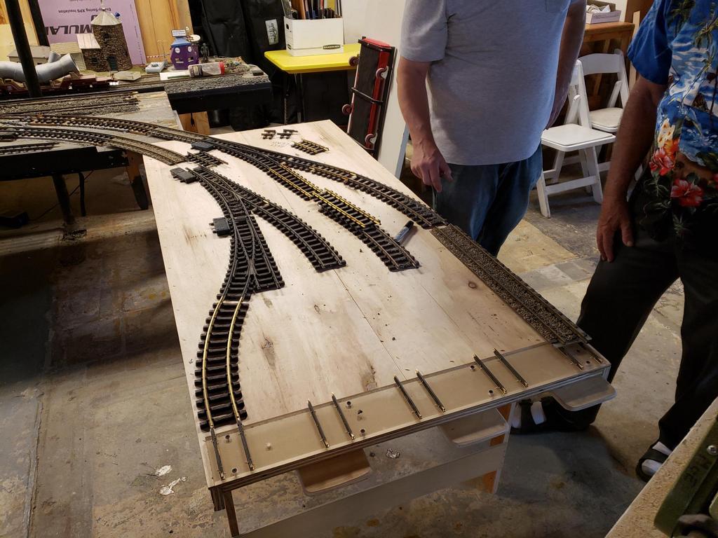
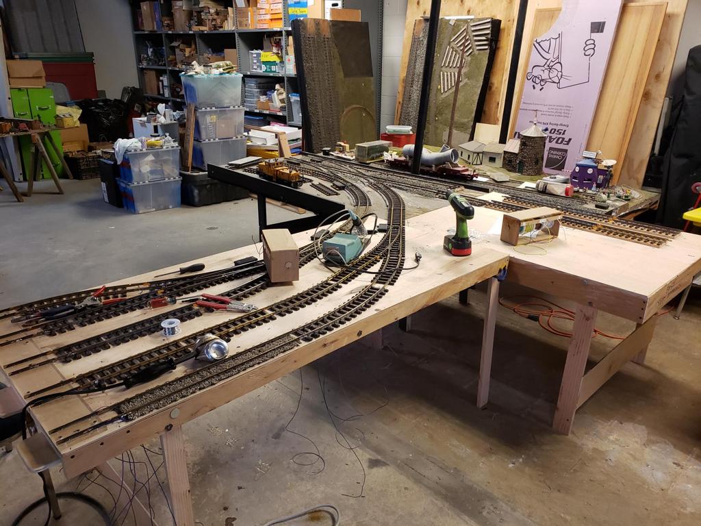
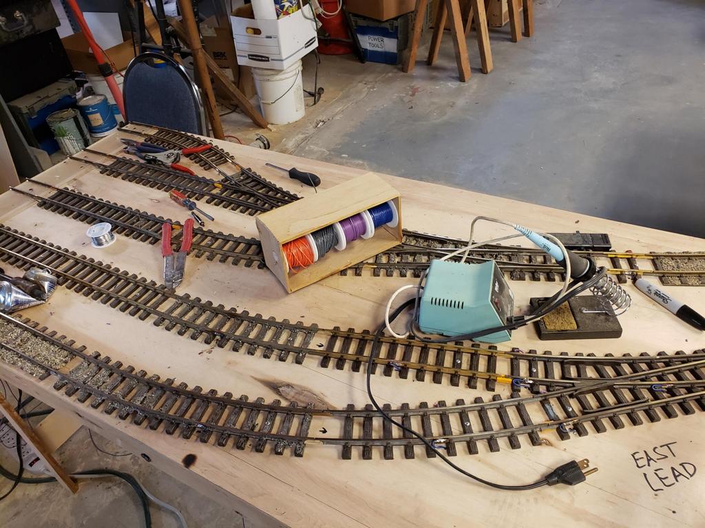
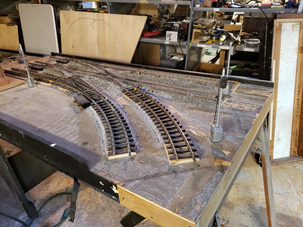 For week 3, we have begun working on the west end of the yard entrance/exit. In this picture and the next, you can see the current state of the east end. |
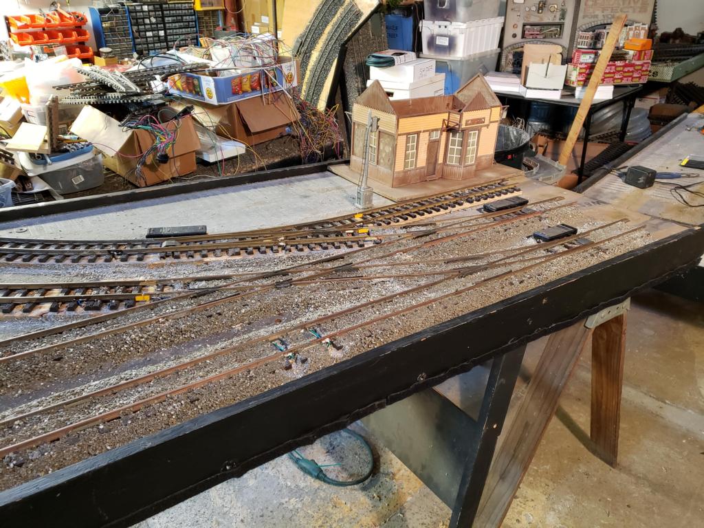 And in this picture, we have added the small freight station which will cover the gap between the west and east ends. |
 In this picture and the next, Eric is working on the track feed locations. |
 |
 And here is a photo of the switch machines, they have been tested and appear to work perfectly. |
|||
| Week 4 | |||
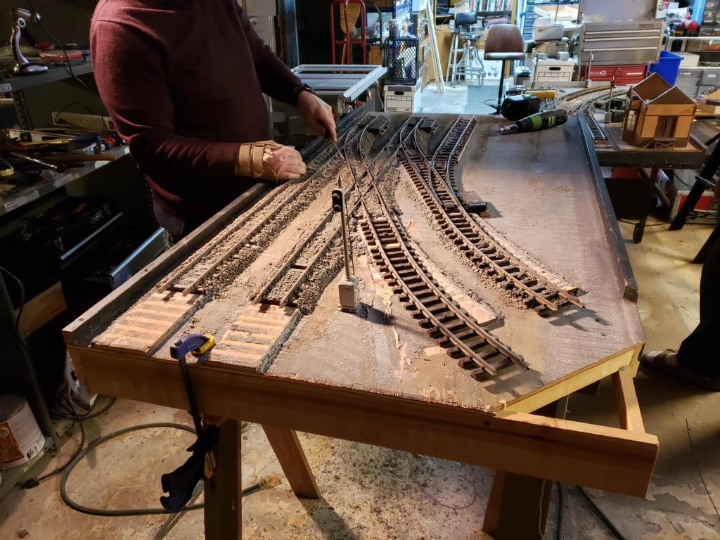
 To start week 4; Bruce, Eric, and I moved the next yard module (west-end) into position. Currently, it is clamped to the west mainline yard module. |
 In this picture, Eric started removing the old track feeds so it is ready for new track feeds. |
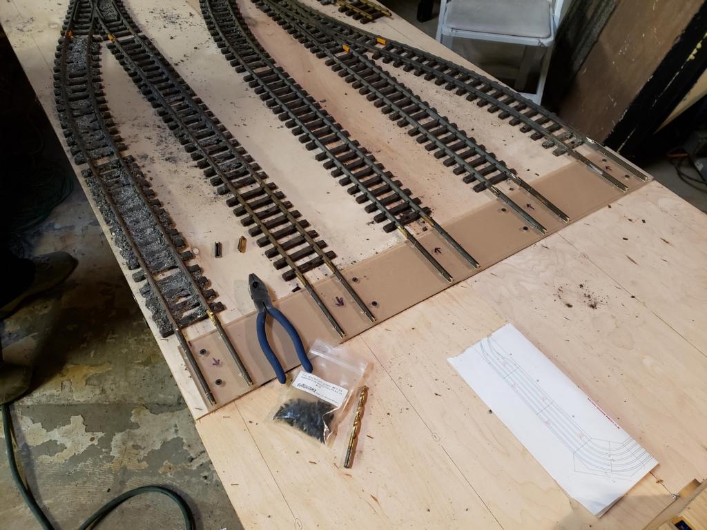
 Here is a closeup of the yard module with the track and isolation joiners installed. |
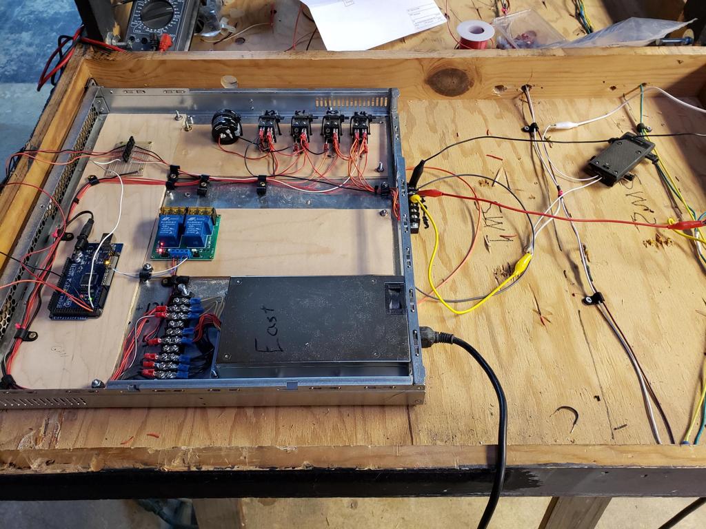
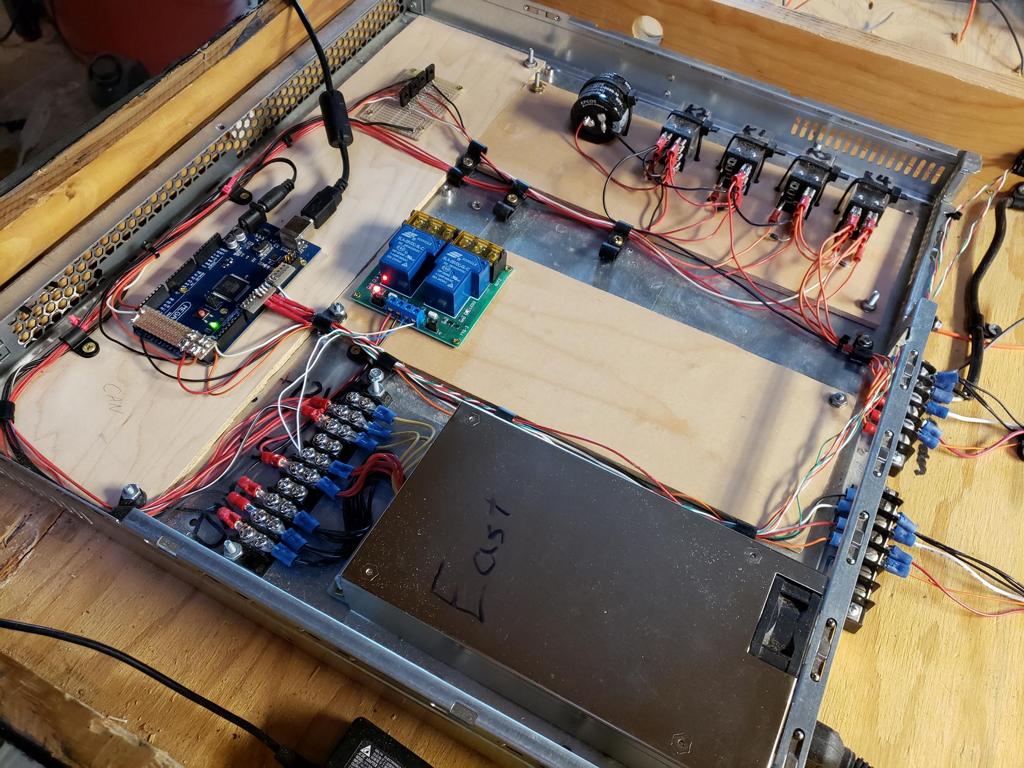
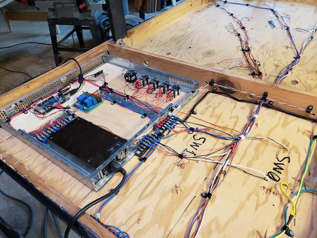
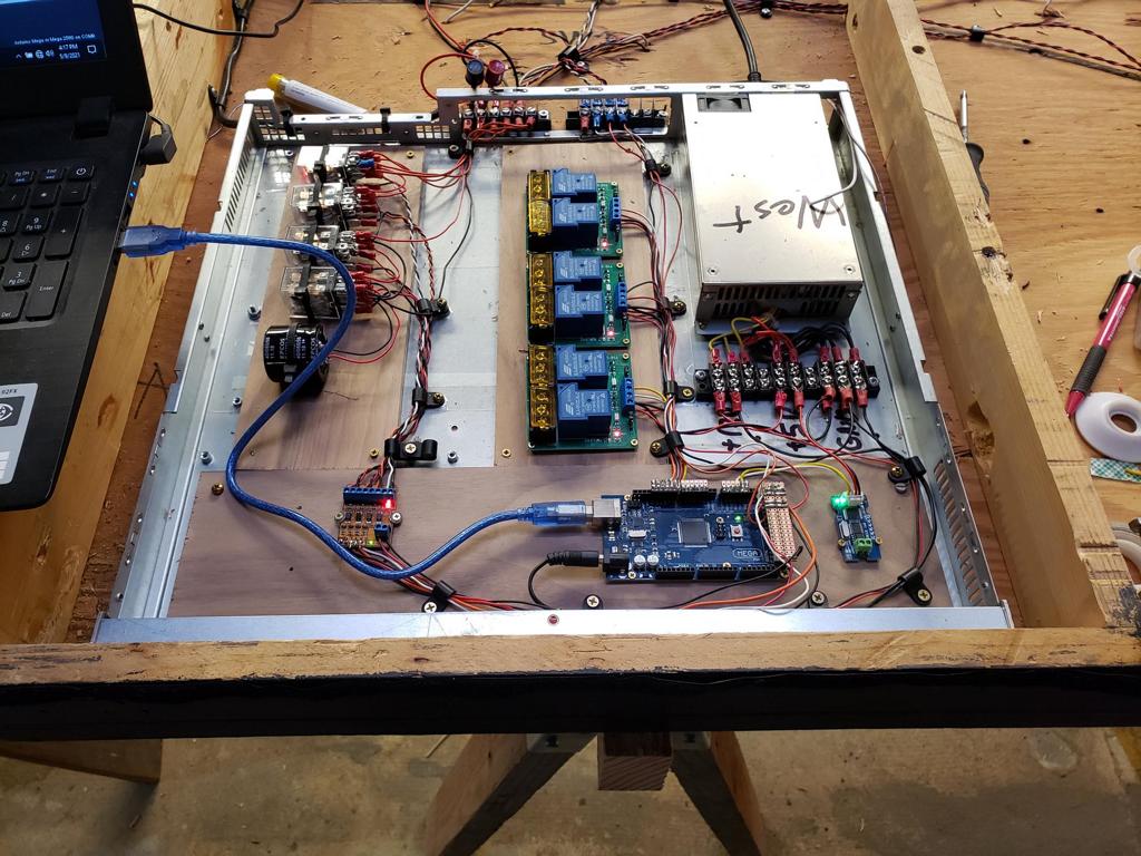
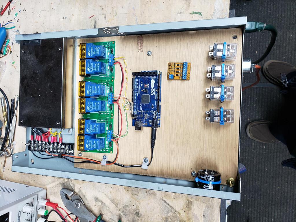
 To finish up this week, I started working on the intelligence for the east mainline yard module. |
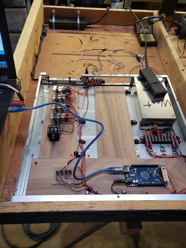
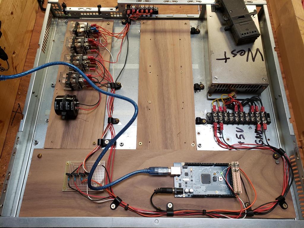
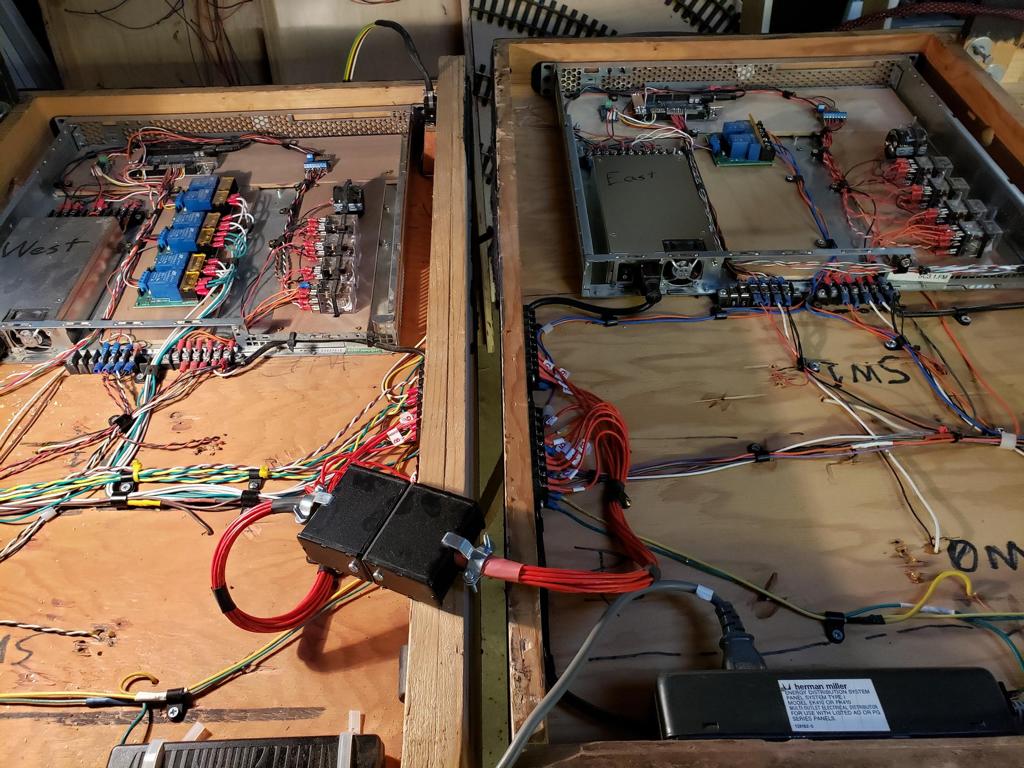
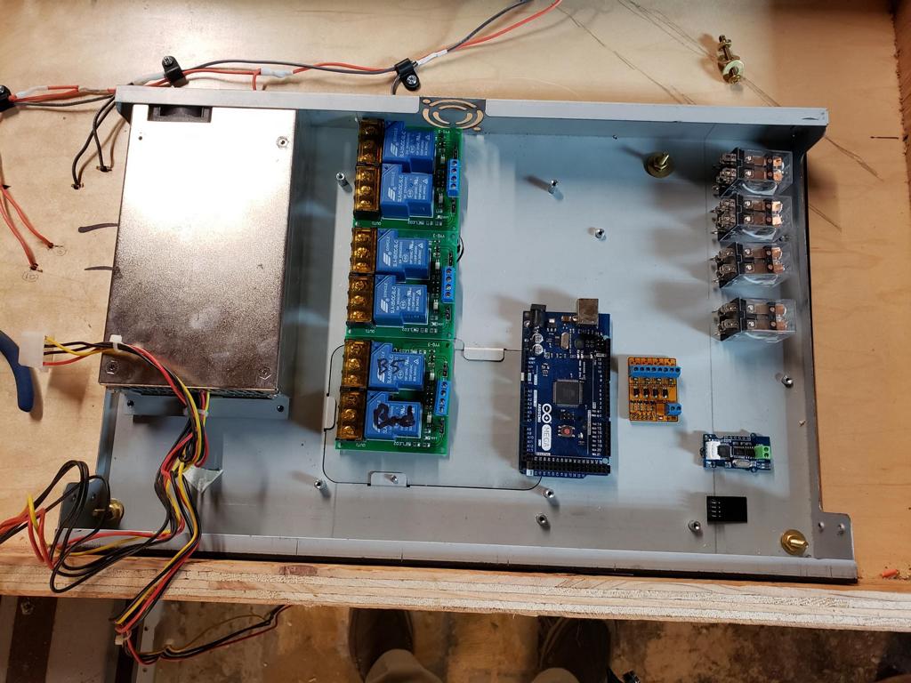
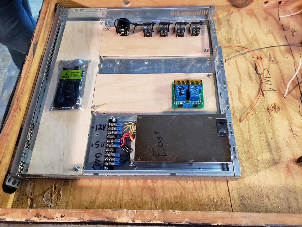 Currently, the intelligence can be broken into four parts. The first (left) part is the intelligence (Arduino Mega) and communication system (CAN-bus). At the top is the second part, the capacitor discharge system which will control the three switches. The capacitor (6800uF 50V) will be charged by a 24VDC computer power supply. In the middle/right, we are using dual relay modules for the track feeds. And finally, the power system for the intelligence is located on the bottom/right. |
|||
| Week 5 | |||
 For week 5, Eric and Bruce continued working on the west-end yard module. To eliminate the need for bridge track, Bruce built a special interface piece which will lock the track in place. Once this was done, Eric cut the track to size and began prepping the module for track feeds. |
 Here is a closeup of the interface piece and the next yard module. |
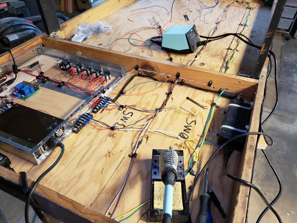
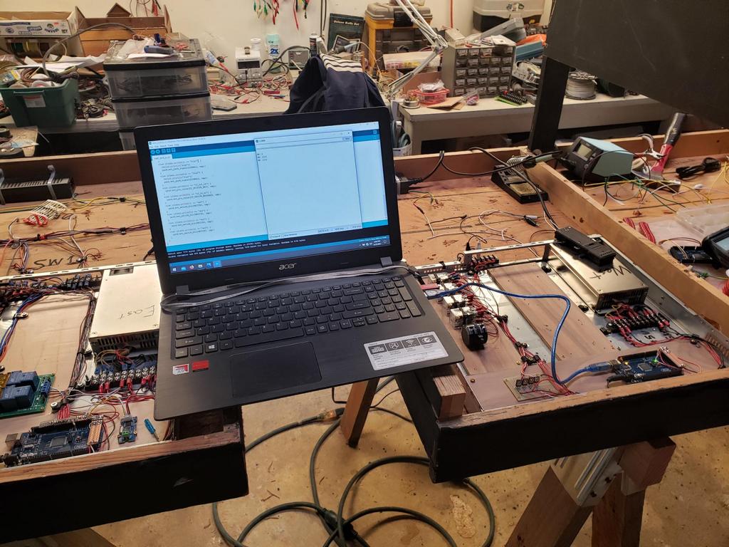
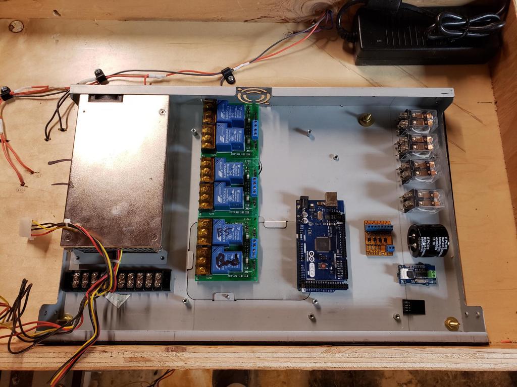
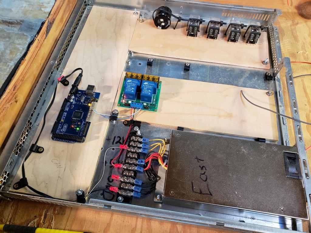 In the case of electronics, I have started adding the intelligence and connecting the track feed relays to the Arduino. |
 To finish up the work, I have connected the track feeds for the mainline on the east-end yard module. These bus feeds have been connected to terminal strips. |
| Week 6 | |||
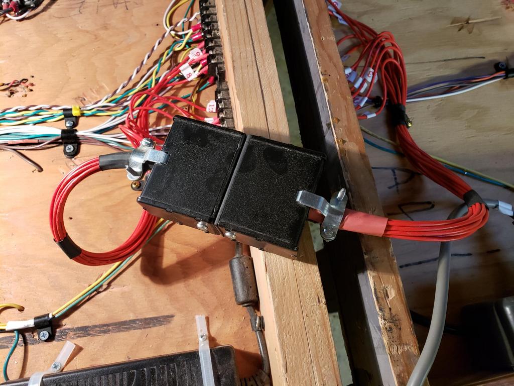
 To start week 6, I started the wiring of the capacitor discharge system for the east mainline yard module. |
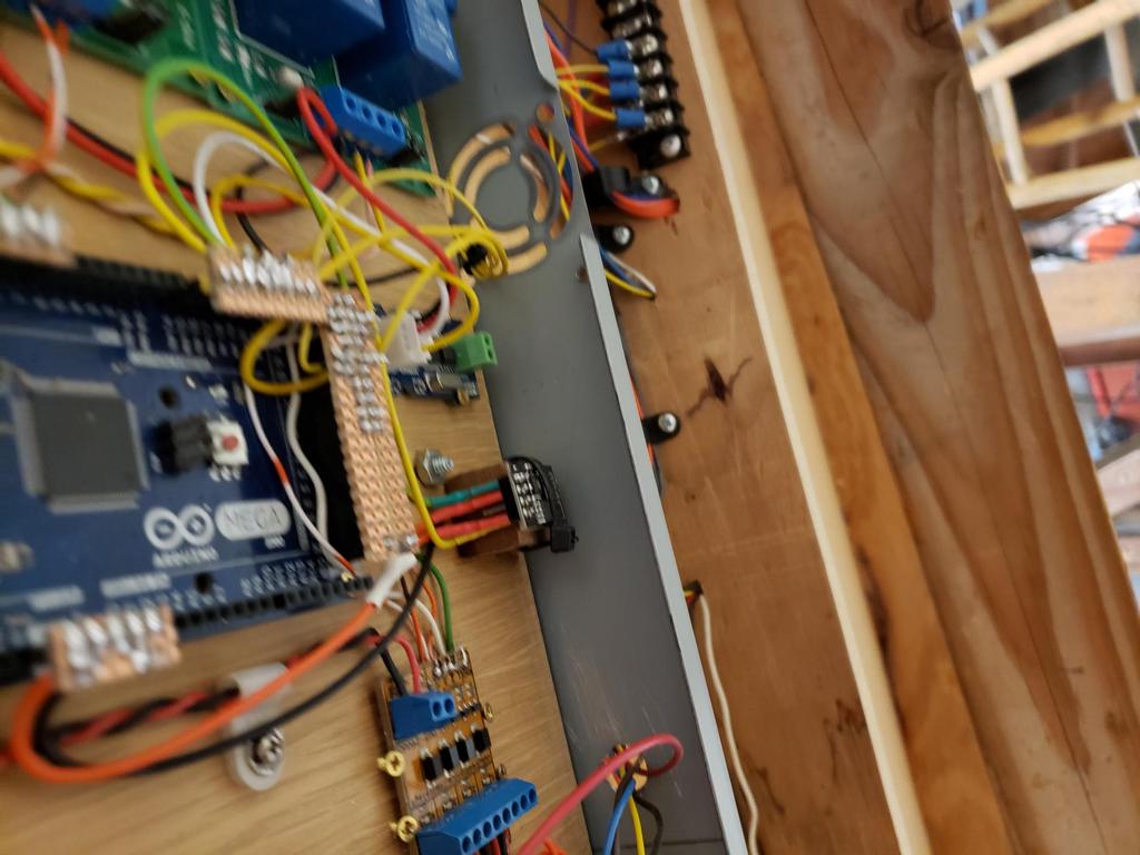
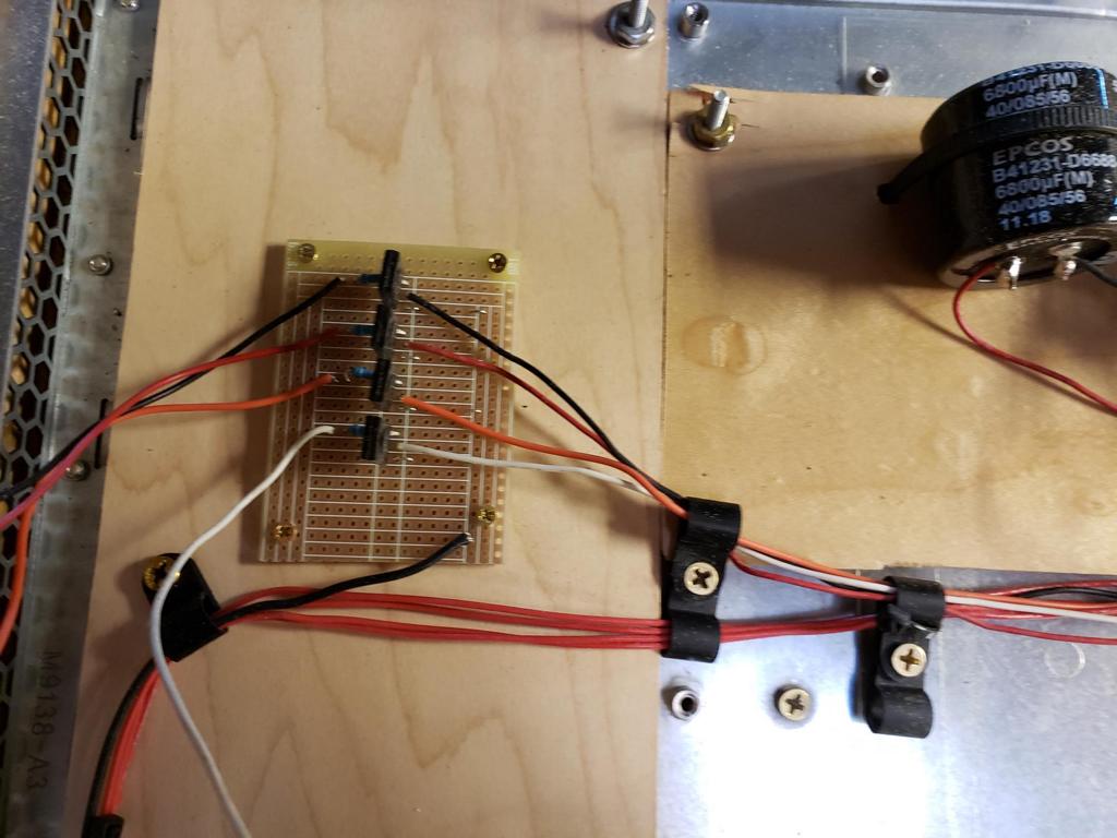 Here is a closeup of the relay driver logic. |
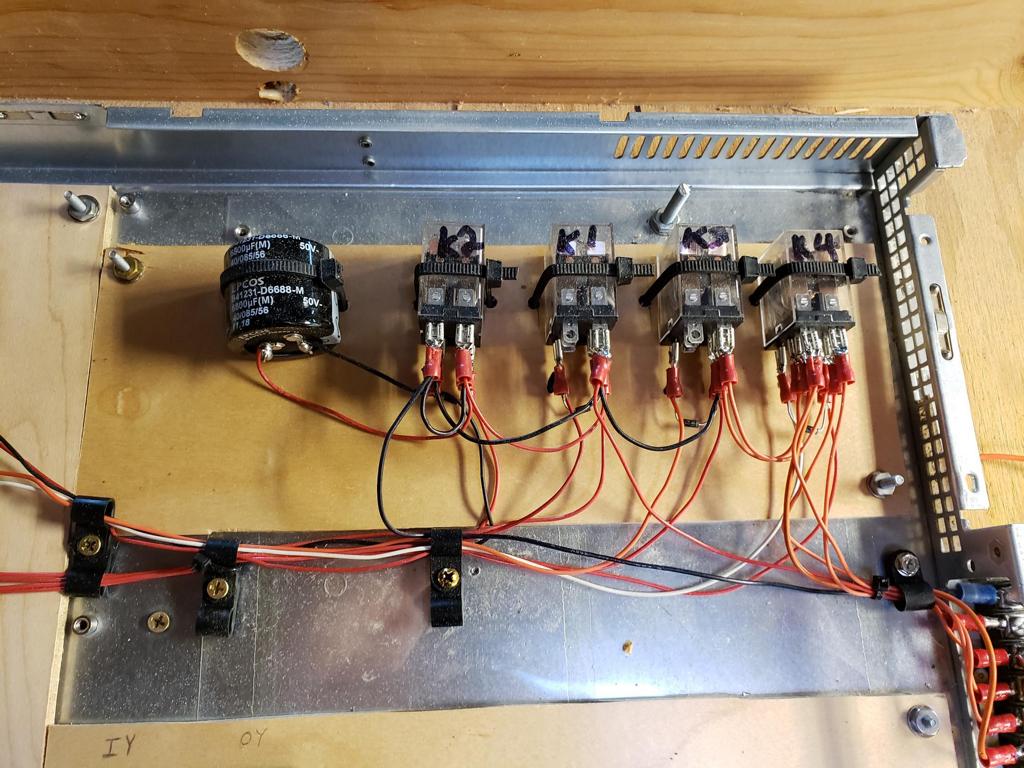 And here is a closeup of the storage capacitor and relays. |
 |
 For week 6, Bruce has been busy assembling the next inner yard modules. |
 Hopefully, we can begin adding the track and track feeds. |
||
| Week 7 | |||
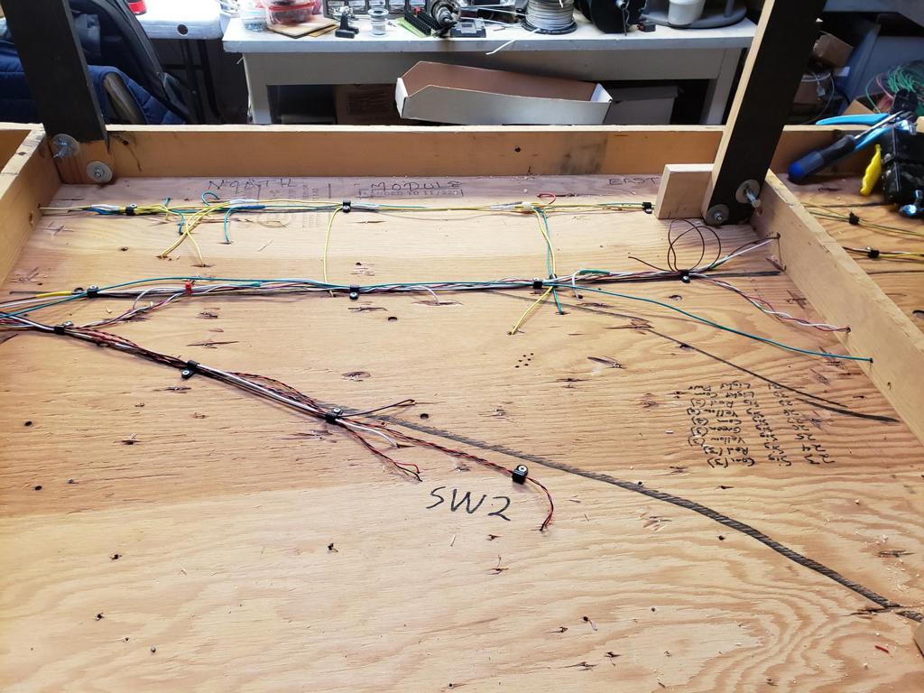
 For week 7, I continued my work on the east mainline yard module. At the end of the day, I completed wiring of the three switches, the feedback modules, and two of the three railroad signals. |
 |
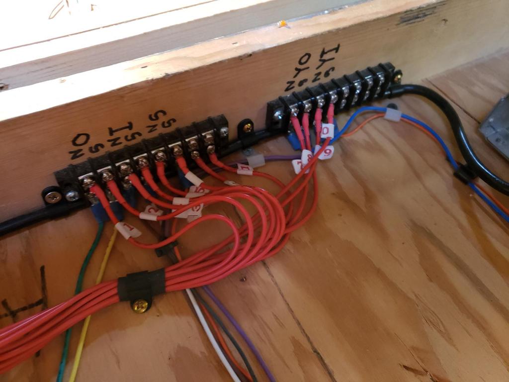
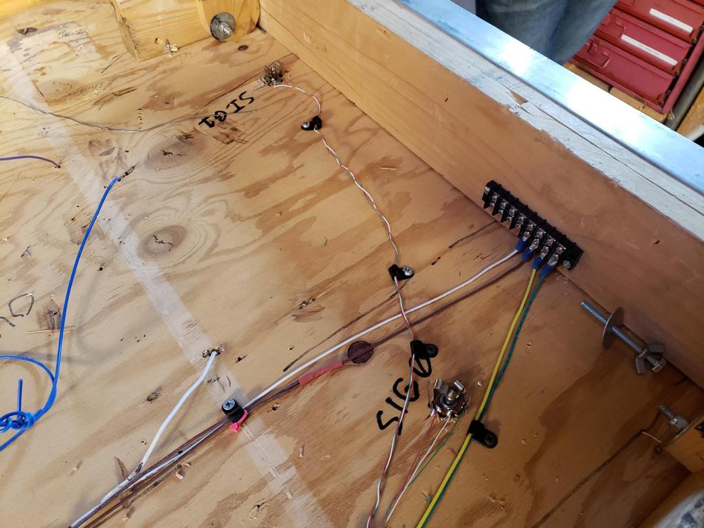 Here is a closeup of the signal wiring and plug assemblies. To help organize the wiring, I have twisted the three wires together (white=5V, green=green, & red=red). |
 And here is a picture of the two signals plugged in. Yes, it is a little strange to see them in this orientation. |
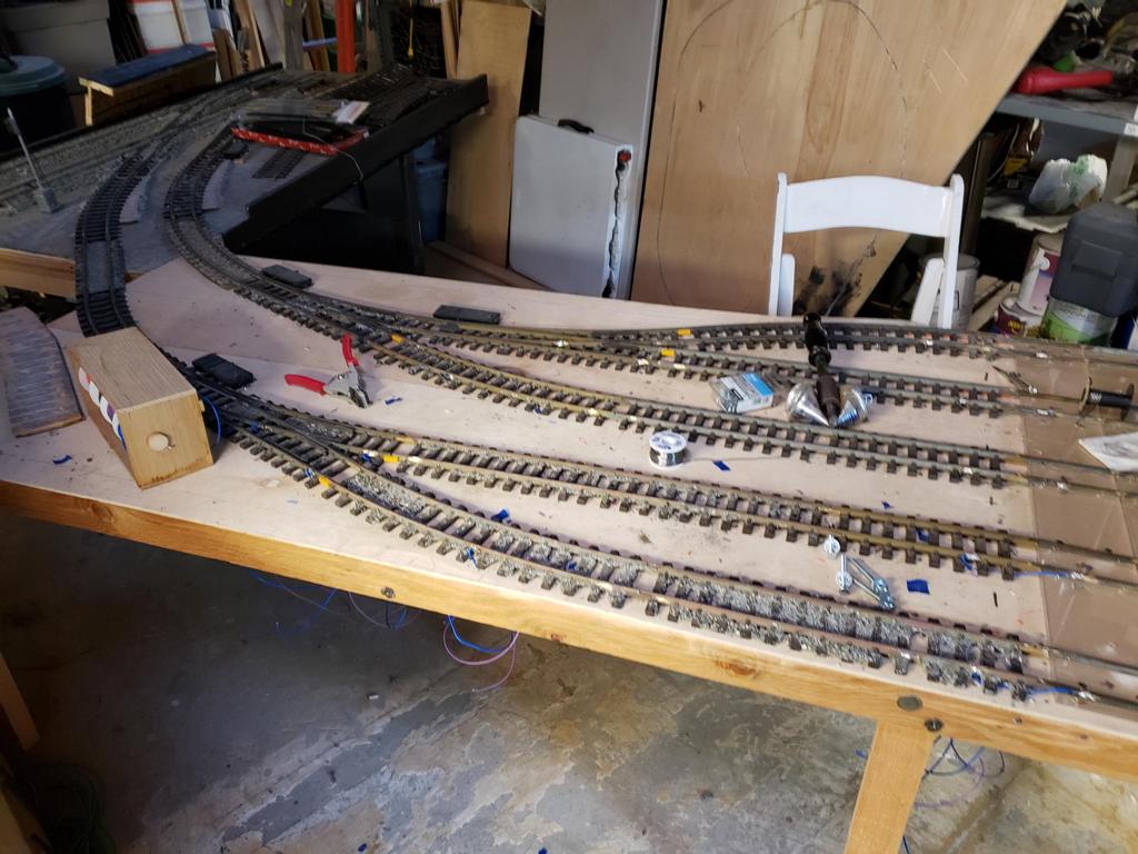 As for the rest of the yard modules, Eric has been busy installing track feeds. |
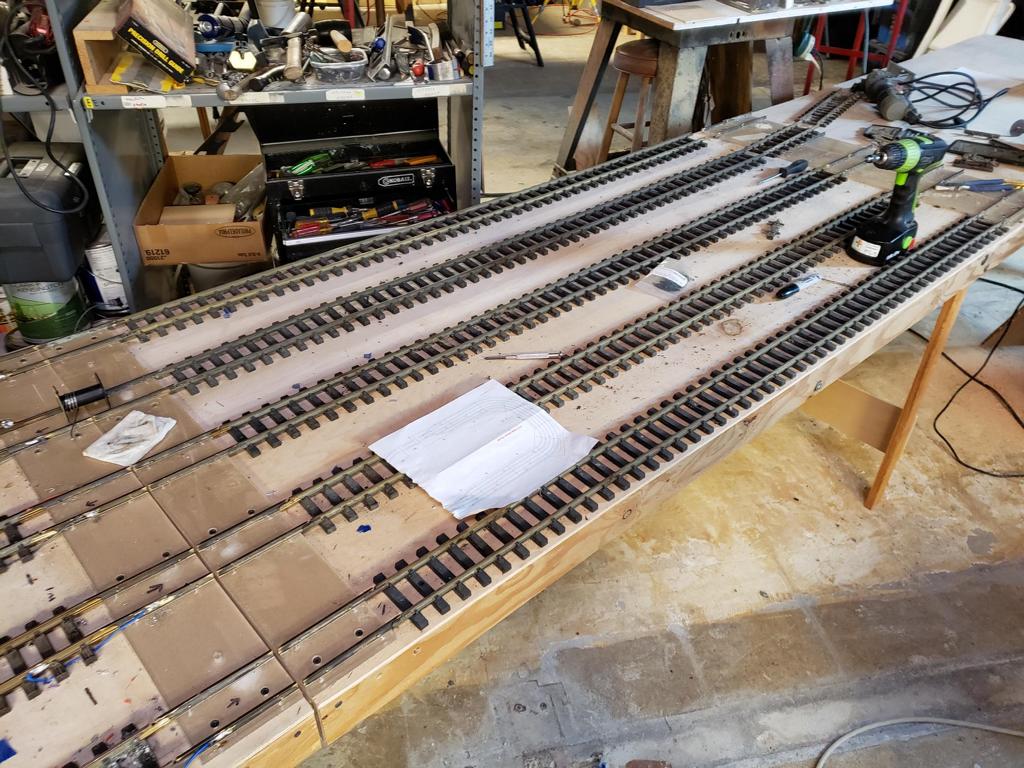 |
 And Bruce has been busy building more of the yard modules (as seen above and in the next picture). |
 |
| Week 8 | |||
 As part of week 8, Eric continued his work on the track feeds and Bruce continued assembling more of the yard modules. |
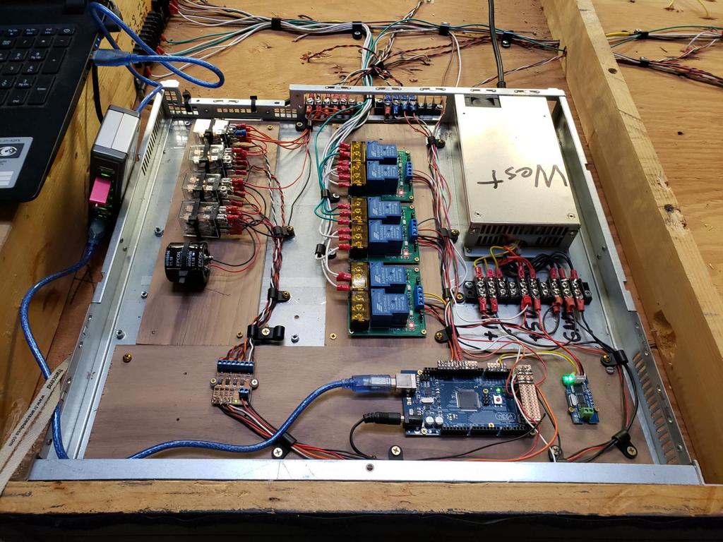
 Continuing my work on the yard intelligence, I was able to complete most of the east yard entrance/exit module. In this picture and the next two, you can seem the completed intelligence and wiring buses. |
 |
 At this point, we are only waiting on the CAN interface boards and the connectors. Once these arrive, we can finish the east yard entrance/exit module and start working on the next yard module. |
 And here are two pictures of the last (third) signal on this yard module. |
 |
||
| Week 9 | |||
 For week 9, I added the CAN bus module to the east yard entrance/exit module and started work on the west yard entrance/exit module. |
 |
 Prior to leaving, I was able to fully test the capacitor discharge system for the west yard module. Next week, I hope to add the track feed relay boards and begin running the wires to the track feeds and switches. |
 In this picture, Eric is finishing his track feed wiring on the next yard section. |
| Week 10 | |||
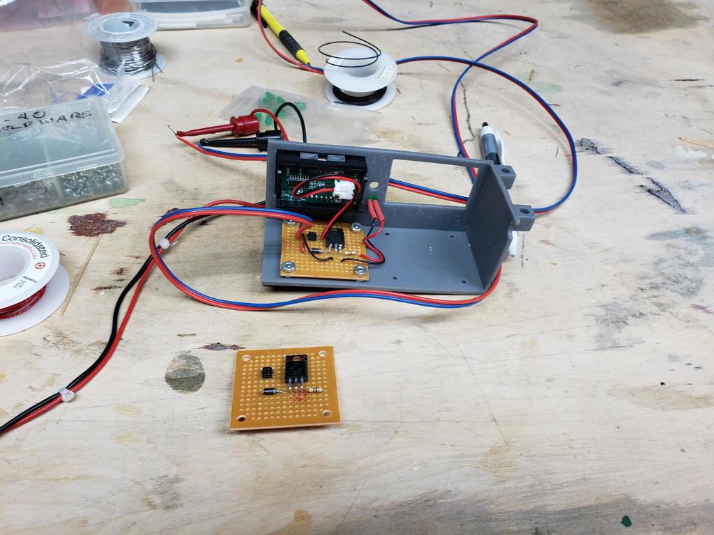
 As part of week 10, I replaced the capacitor discharge relay driver board and started adding the track feed relay boards. |
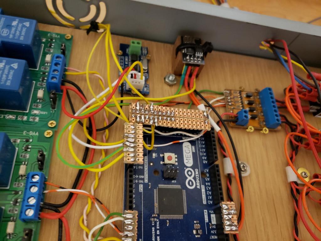
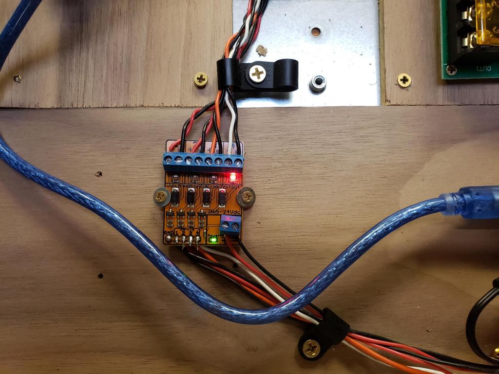 Here is a closeup of the new relay driver board. It has a number of diagnostic LEDs to assist with debugging potential issues. |
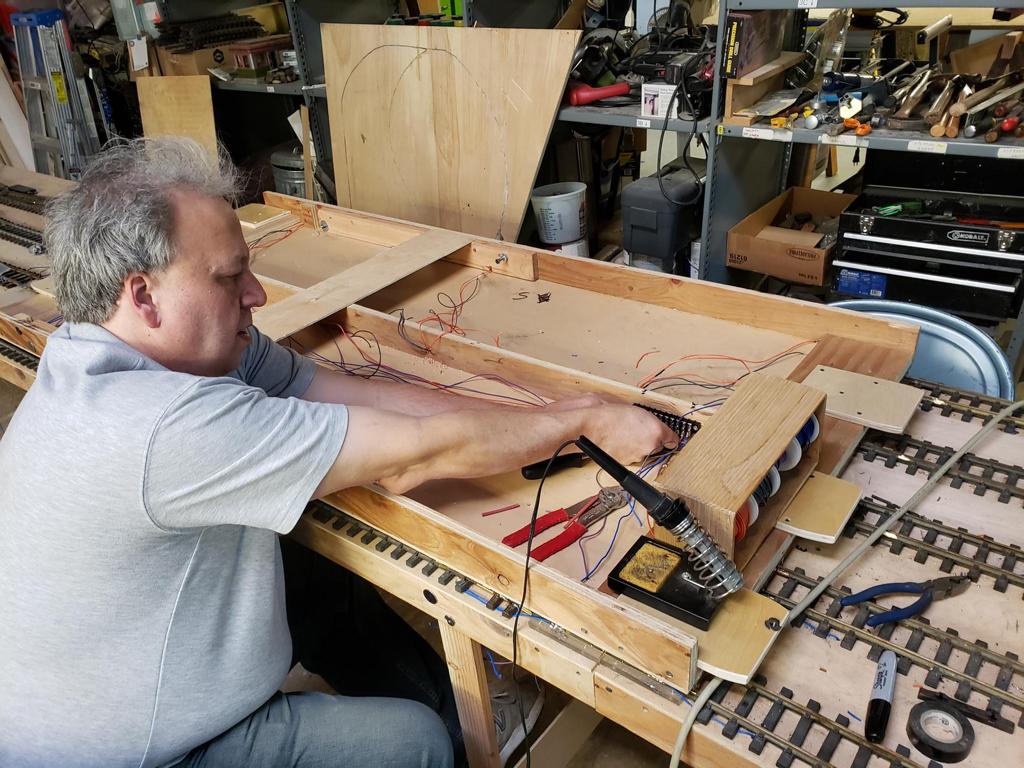 And here is a photo of Eric who is currently working on the electrical bus for one of the yard modules. |
|
| Week 11 | |||
 For week 11, I have wired up the track feeds and retested the switch capacitor discharge system on the West end of the yard. |
 Since the relay driver boards have arrived, I have replaced the homemade driver board on the west/east end of the yard. These boards are optically isolated and have additional LEDs which can be used for diagnosing potential issues. |
 And here is the wiring for the track feeds, switches, and signal. |
 In this picture, Eric is finishing one of the inner yard modules by removing any sharp screw edges. |
| Week 12 | |||
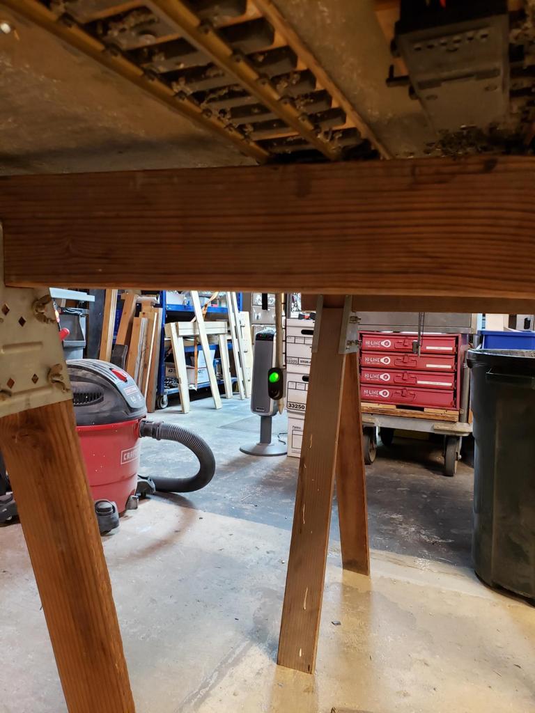
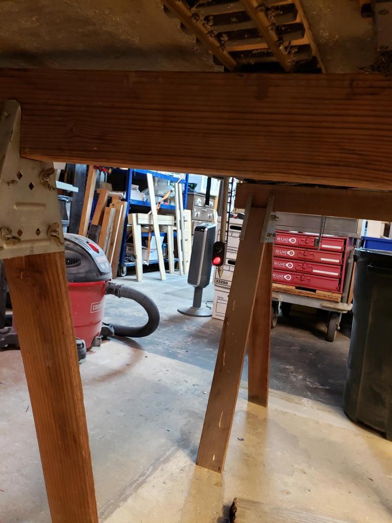
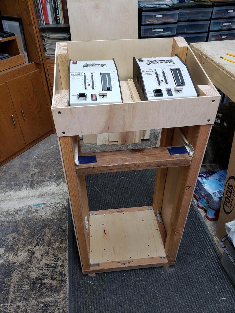
 After a short pause, I have resumed work on the yard. As part of week 12, I have started construction of the tower for the yard. |
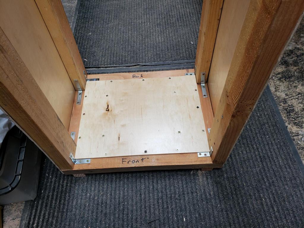 Here is a closeup of the base. It has two "feet" that allow easy transportation by hand truck. |
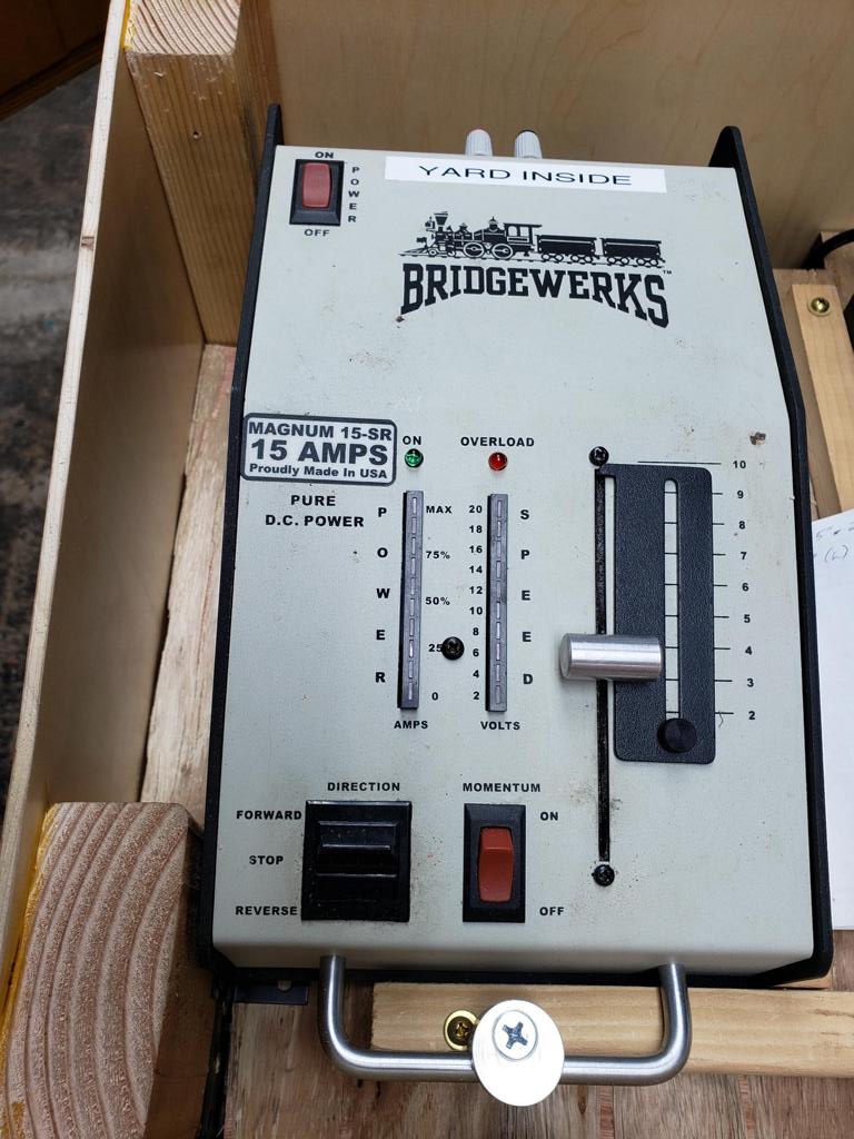
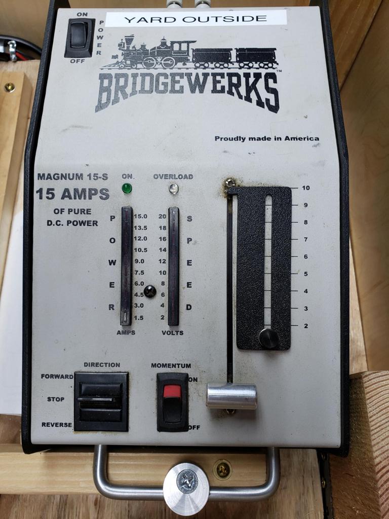
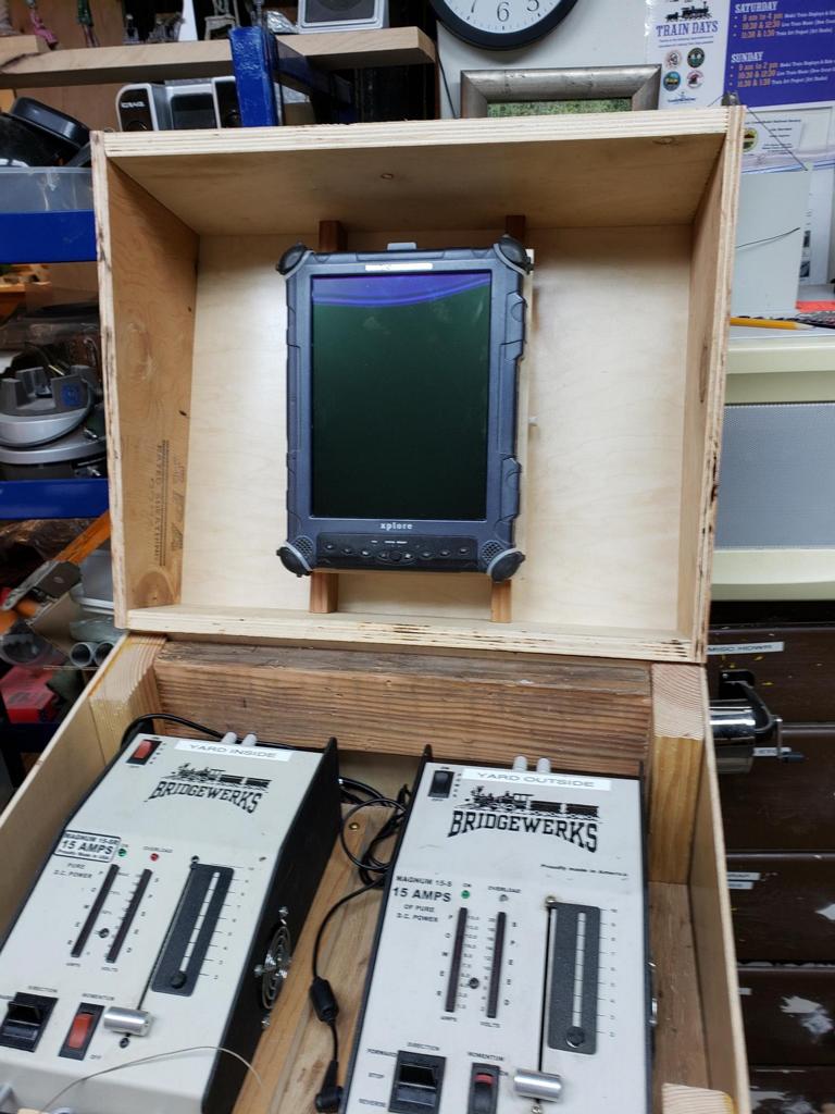
 The yard tower will feature two 15 Amp Bridgewerk power supplies, a rugged tablet, and miscellaneous electronics for communicating with the yard modules. |
 For week 12, Bruce and Eric started working on the next yard module (east-end). It is currently clamped to the east mainline yard module. |
 In the coming weeks, the rest of the track will be added and track feeds will be installed. |
|||
| Week 13 | |||
 For week 13, I have continued my work on the yard tower. This includes additional cross beams, the front and back top plates, and the top shelf for the Bridgewerks. |
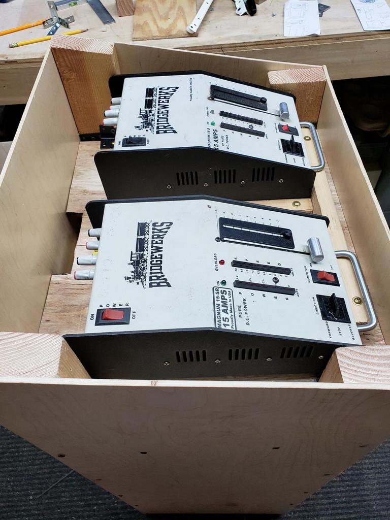 Here is a closeup of the Bridgewerks and the cable slot for feeding power and communication cables. |
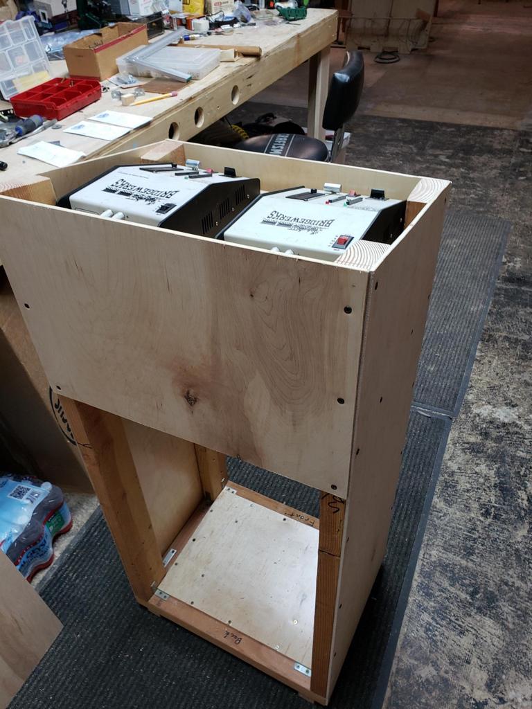 And here is the back view. |
 For week 13, we tested the east yard entrance/exit and Eric has started adding the electrical drops. |
 |
|||
| Week 14 | |||
 For week 14, Bruce created/installed locking mounts for the Bridgewerks power supplies. |
 |
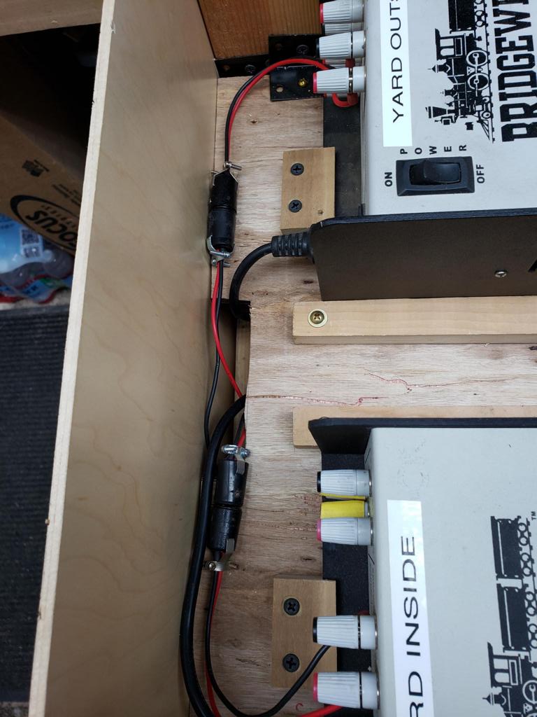 Since the power supplies are secure, I have started the wiring process. Here is a picture of the connectors and power cables. |
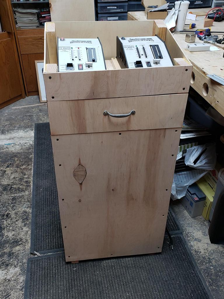 In this picture, I have installed the finished drawer. |
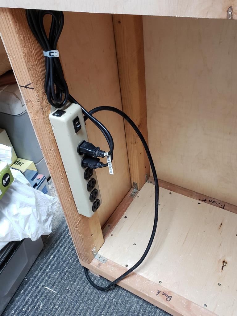 And in this picture, the power strip has been mounted. |
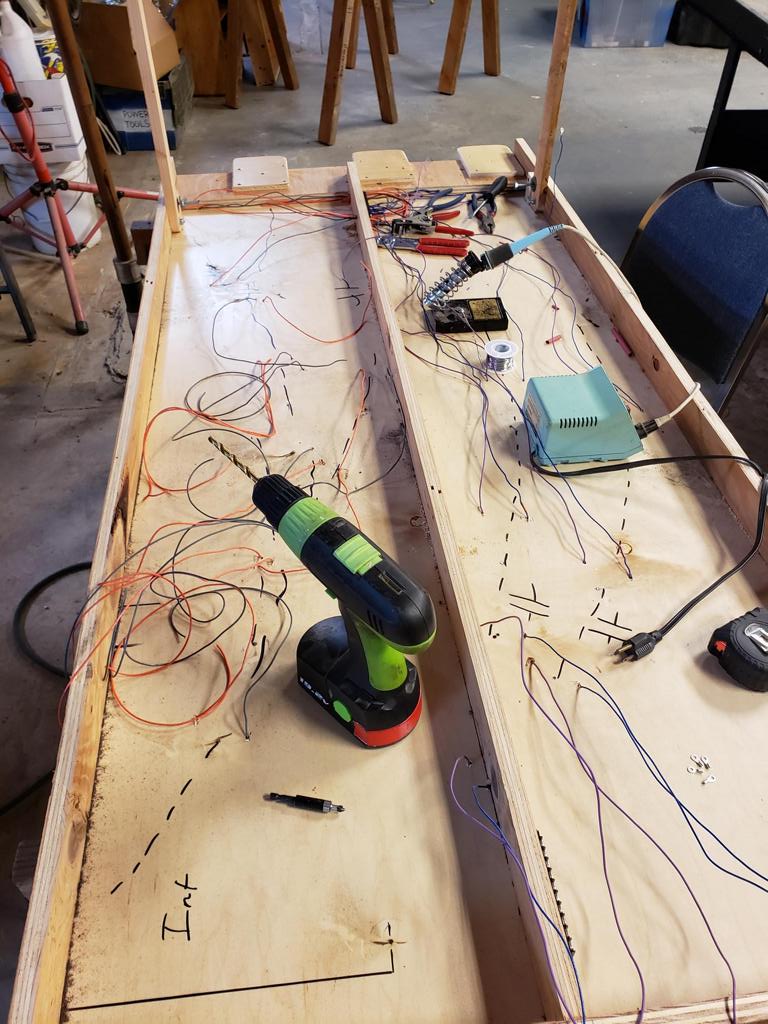 To finish week 14, Eric started working on the bus feeds on the east yard leg. |
||
| Week 15 | |||
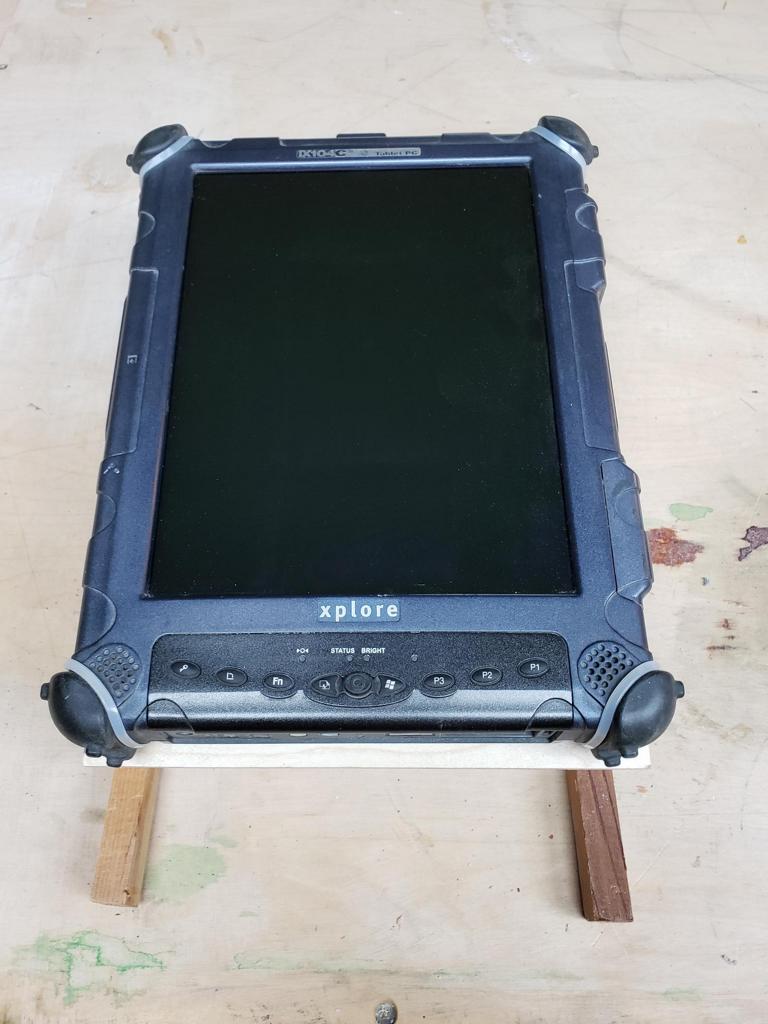 For week 15, I started working on the adjustable mounts for the rugged tablet. These mounts should allow the operator to adjust the screen angle. |
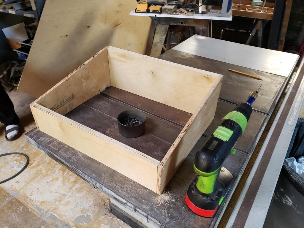 With the finished mounts, I could fabricate the top shell for the yard tower. |
 Here is the finished top shell. All it needs is the installation of the piano hinge. |
 Finishing up week 15, Eric is working on one of the last of the yard straight modules. |
| Week 16 | |||
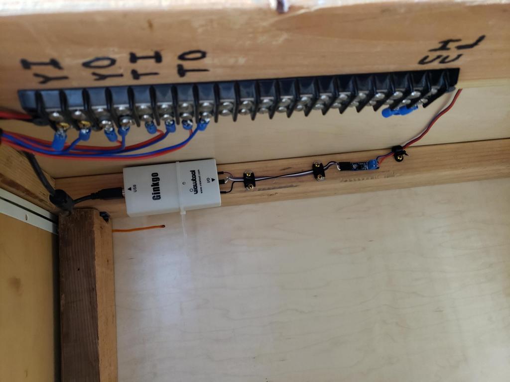
 Starting week 16, I began installing some of the peripheral equipment for the yard tablet. This includes a small USB hub, the stylus holder, and the USB-to-CAN bus adapter. |
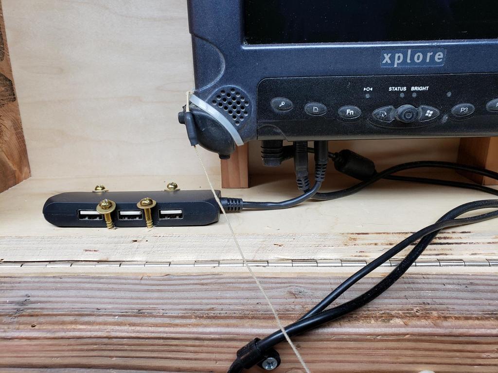 Here is a closeup of the USB hub. |
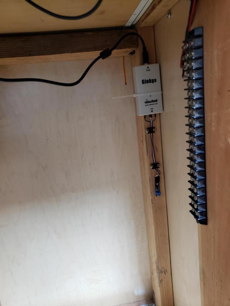 And here is the USB-to-CAN bus adapter. |
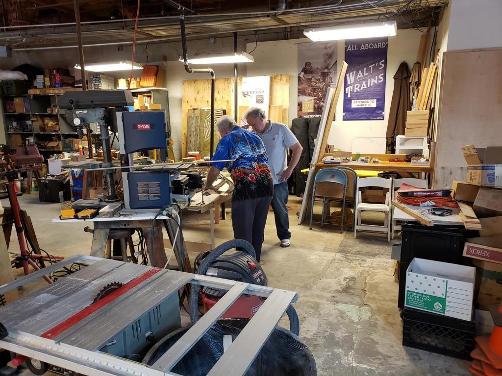
 To finish up week 16; Bruce, Eric, and myself started working on the first yard corner. |
| Week 17 | |||
 After a fairly long hiatus, I have resumed the wiring of the yard. Here is an inside look at one of the voltage monitors. |
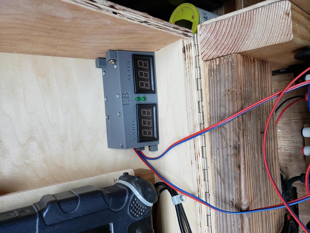 These voltage monitors should allow us to match the voltage of the yard power supplies with the voltage from the TOP. |
 And here is the wiring of the terminal strip. |
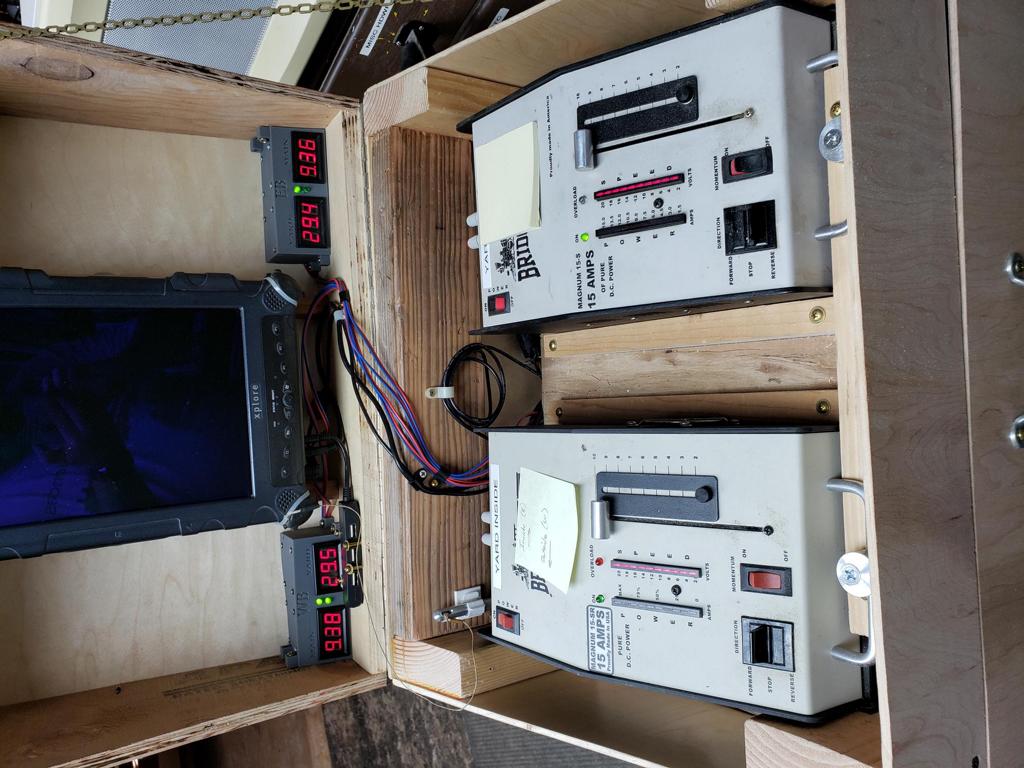 Finishing up week 17, this is a picture of the monitor testing. The LEDs will provide direction sensing while the meter shows voltage. |
| Week 18 | |||
 For week 18, I added the connectors to relay the power and track feeds between the west and east yard entrance/exit modules. |
 |
 Here is a close-up of the terminal strips. |
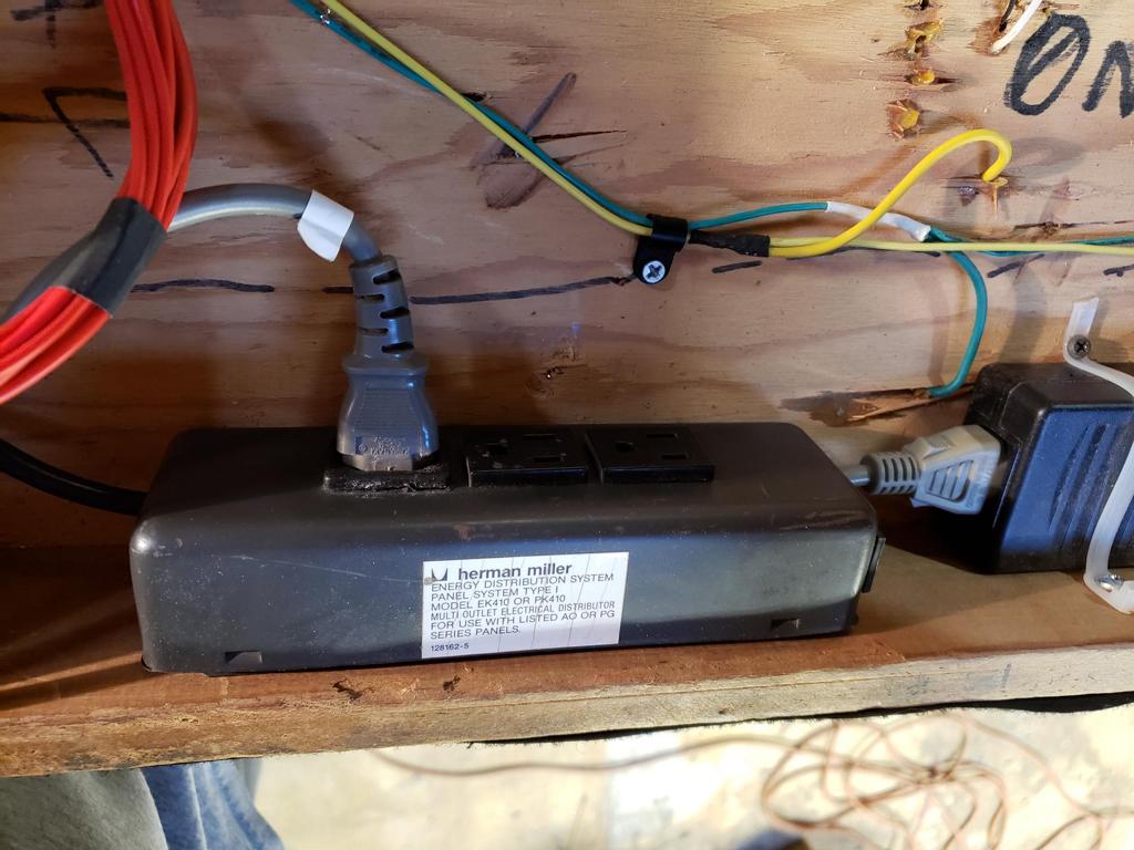 To finish up, I installed a modified power strip which replaces the cable with an IEC power receptacle. |
| Week 19 | |||
 Since I have finished testing and bug fixing on the yard entrance/exit modules, it is now time to start working on the inner yard modules. To start week 19, I decided to layout the components inside the computer shell. |
 By laying out the components, I can decide where to place mounting holes and through-holes for wiring. |
 And here is the computer shell with a mounting board and some of the components mounted. |
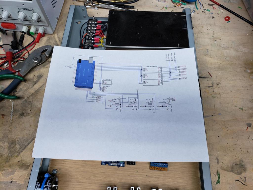 Here is a quick schematic of the intelligence. The intelligence has an Arduino Mega, two communication interfaces (CAN and WiFi), track power boards, and a capacitor discharge system. |
| Week 20 | |||
 For week 20, I finished work on the intelligence for the west yard throat area. That leaves only one intelligence module to finish for the yard area. |
 |
 And here is a photo of the west yard entrance and west yard throat. The small LGB porter was used to test the track feeds and switches. |
 Finally, I started wiring up the intelligence for the east yard throat area. So far, the module appears to respond correctly to commands from the yard tower. |